How to Build a VHF Yagi Antenna Using PVC Pipe, Metal Tape Measure, and a Hairpin Match with Integrated Coax Connection
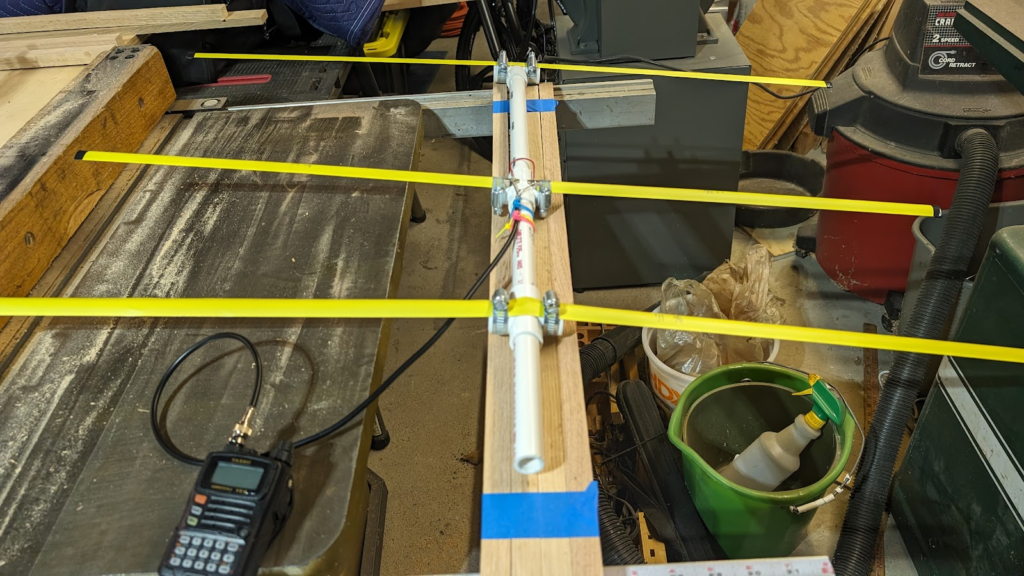
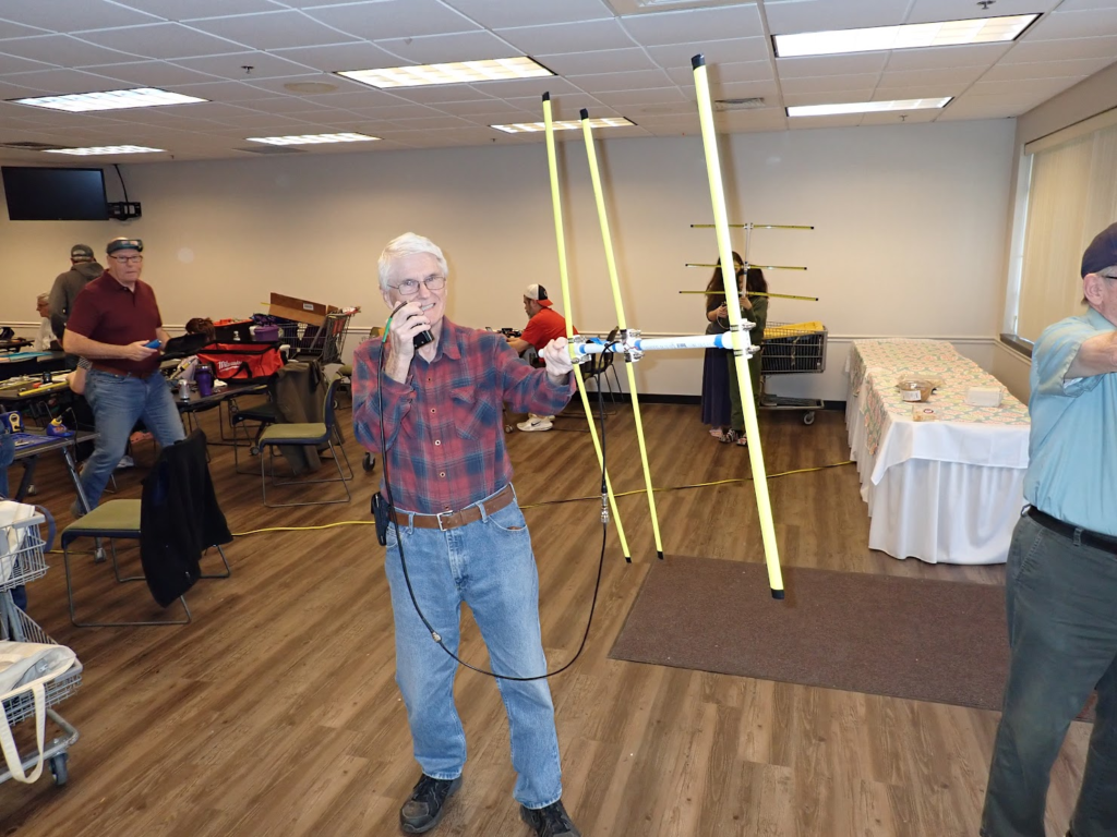
This guide will show you how to build a compact, effective VHF Yagi antenna using PVC pipe, a metal tape measure for the elements, and a hairpin match integrated with the coaxial cable connections. The antenna design includes PVC pipe fittings for mounting stability, with a T-joint for the director and cross-sections for the driven element and the reflector/handle. This design makes assembly easier and allows for more precise element alignment.
Materials Needed
For the Antenna:
- PVC Pipe (1/2″ or 3/4″): Used as the boom.
- Metal Tape Measure (1″ wide): To create the reflector, driven element, and director.
- Coaxial Cable (RG-58 or similar): Connects the antenna to the radio or receiver.
- SO-239 Coax Connector: For easy attachment to the radio.
- 12-Gauge Solid-Core Copper Wire: To create the hairpin match.
- PVC T-Joint (1): For mounting the director.
- PVC Cross Section (2): One for the driven element and one for the reflector and handle.
- Electrical Tape or Heat Shrink Tubing: For insulating the connections.
- Zip Ties or Screws: To secure the elements to the PVC pipe.
Tools Required:
- Measuring Tape
- Hacksaw or Metal Snips
- Drill with 1/4″ or 1/2″ drill bit
- Soldering Iron and Solder
- Sandpaper
- Marker
Step-by-Step Guide
Step 1: Element Dimensions
For a VHF Yagi antenna tuned to the 2-meter band (144-148 MHz), the elements should be cut to the following lengths:
- Reflector: 1.04 meters (40.94 inches)
- Driven Element: 1.00 meter (39.37 inches), split into two sections, each 0.50 meters (19.68 inches) long
- Director: 0.95 meters (37.40 inches)
Spacing between elements:
- Reflector to Driven Element: 0.25 meters (9.84 inches)
- Driven Element to Director: 0.20 meters (7.87 inches)
Step 2: Cut the Elements
- Measure and cut the following lengths from the metal tape measure:
- Reflector: 1.04 meters (40.94 inches)
- Two sections for the driven element: Each section should be 0.50 meters (19.68 inches).
- Director: 0.95 meters (37.40 inches)
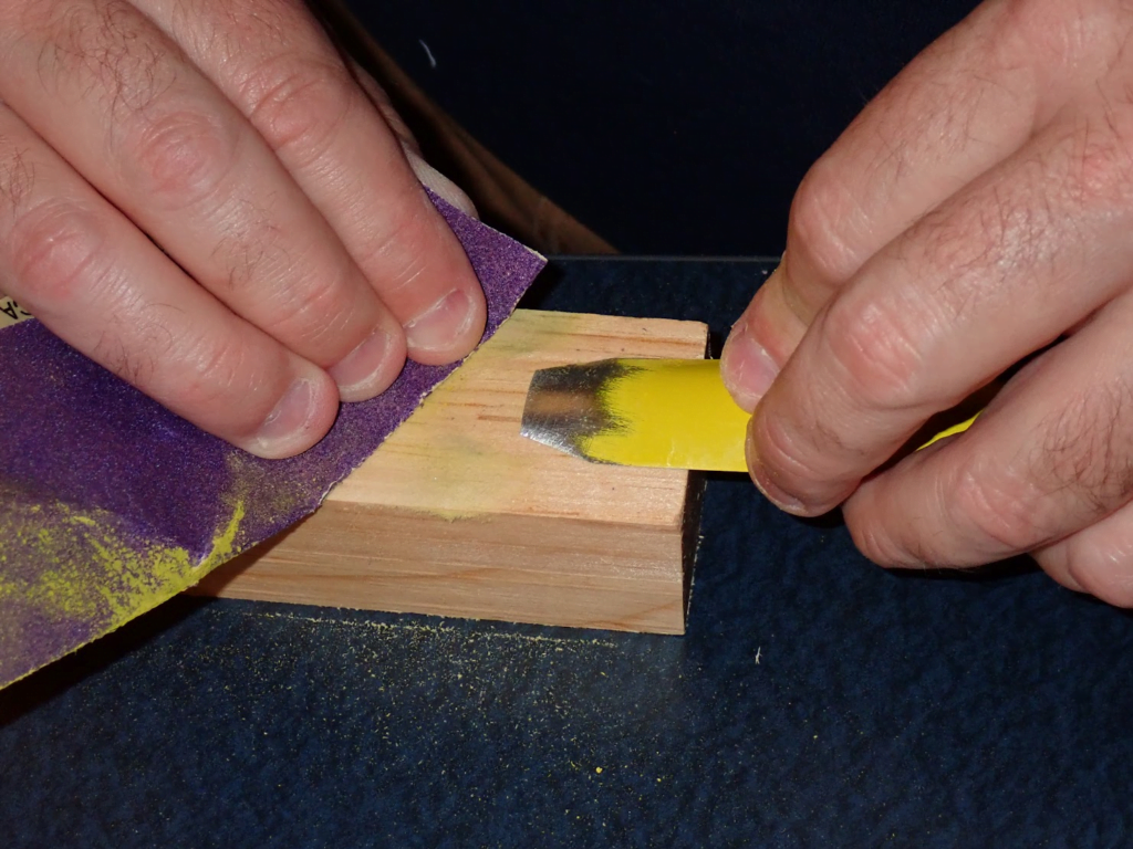
- Sand the edges of the metal pieces to remove any sharp burrs.
Step 3: Prepare the PVC Boom
- Cut a PVC pipe to approximately 1.0 meter (39.37 inches) in length. This will include space for the elements and a handle.
- Mark the positions on the PVC pipe where each element will be mounted:
- The reflector at one end
- The driven element 0.25 meters (9.84 inches) from the reflector
- The director 0.20 meters (7.87 inches) from the driven element
Step 4: Install PVC Connectors
T-Joint for Director
- At the mark for the director, insert the T-joint into the PVC boom.
- The horizontal section of the T-joint will hold the director perpendicular to the boom.
Cross Section for Driven Element
- At the driven element position, insert a PVC cross-section.
- The two halves of the driven element will be mounted in the horizontal openings of the cross-section, with the boom passing through the vertical axis.
Cross Section for Reflector and Handle
- At the reflector position, insert the second PVC cross-section.
- The reflector will be mounted in the horizontal openings, and the bottom vertical opening will hold a PVC pipe piece (~20 cm / 8 inches long) to act as a handle.
Step 5: Mount the Elements
- Insert the reflector, driven element, and director into the appropriate PVC connectors (crosses and T-joint).
- Use zip ties or screws to hold the elements securely in place, ensuring they are perpendicular to the boom.
Step 6: Connect the Coaxial Cable and Hairpin Match
Coaxial Cable Connection
- Solder the Coaxial Cable:
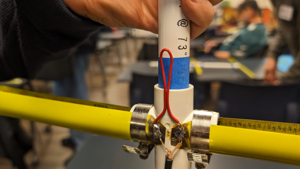
- Solder the center core of the coaxial cable to one half of the driven element.
- Solder the ground/shield of the coaxial cable to the other half of the driven element.
Hairpin Match (12-Gauge Solid-Core Copper Wire)
- Cut a piece of 12-gauge solid-core copper wire to approximately 16-20 cm (6-8 inches) long.
- Bend the wire into a U-shape, leaving a 2-3 cm (1 inch) gap between the ends.
- Solder one end of the hairpin match to the same point where the center core of the coax is attached to the driven element.
- Solder the other end of the hairpin match to the same point where the coax ground is attached to the other half of the driven element.
This placement ensures the hairpin is installed in parallel with the coax connections, maintaining a neat and efficient design.
Step 7: Attach the Coaxial Cable and Connector
- Run the coaxial cable through the handle at the reflector end using the PVC cross-section for easy access.
- Solder the other end of the coaxial cable to the SO-239 connector, allowing you to connect the antenna to your radio or receiver.
Step 8: Test and Fine-Tune the Antenna
- Use an SWR meter to test the antenna’s performance on the 144-148 MHz band.
- If necessary, adjust the length of the hairpin match by bending or trimming it slightly based on your SWR readings:
- If the SWR is too high at the lower end (144 MHz), shorten the hairpin.
- If the SWR is too high at the upper end (148 MHz), lengthen the hairpin slightly.
Step 9: Secure and Weatherproof the Connections
- Use electrical tape or heat shrink tubing to insulate and weatherproof the soldered connections.
- Ensure all elements are securely mounted on the PVC boom, and all connections are tightly sealed to prevent damage from weather.
Benefits of This Design
- Neat Coax and Hairpin Match Integration: By placing the hairpin match at the same points as the coax connections, the design is simplified and compact, reducing unnecessary wiring.
- Stable Mounting with PVC Connectors: Using PVC T-joints and cross-sections provides a stable structure for the elements and allows for easy alignment and mounting.
- Easy-to-Build: This method allows you to pre-cut all elements and assemble them in a straightforward, organized manner, making the build process smoother.
Final Build Dimensions
- Total Boom Length: ~1.0 meter (39.37 inches), including a 20 cm (8-inch) handle.
- Element Lengths:
- Reflector: 1.04 meters (40.94 inches)
- Driven Element (pre-cut): 0.50 meters (19.68 inches) per side
- Director: 0.95 meters (37.40 inches)
- Hairpin Match: 16-20 cm (6-8 inches) of 12-gauge solid-core copper wire, bent into a U-shape.
This design gives you a robust, stable, and easy-to-build VHF Yagi antenna, well-suited for amateur radio use on the 144-148 MHz band. By integrating the hairpin match with the coax connections, you maintain a cleaner build while optimizing the antenna’s performance.


Resources and Credit goes to:
http://nt1k.com/blog/2012/vhf-3el-tape-measure-yagi/